MagicBullettm DIY Enclosure - How To Guide
Several people expressed a desire to purchase the MagicBullettm sans the enclosure so they could either make their own or use something else. Since the enclosure is made from common PVC tubing, ends caps, CAT5 cable and connectors, all of which can be purchased at hardware stores such as Lowe's and Home Depot, this is something that the average person could do.
Supplies and tools needed:
Drill (drill press is better)
Soldering iron or gun and solder
Saw or PVC pipe cutter
¾ inch PVC pipe 200psi pressure pipe (not schedule 40 which is too thick)
¾ inch PVC end caps 2 for each protector
PVC cement
Liquid tape or other heavily pigmented coating
Ethernet cable, connectors and crimping tool
Optional: ¼ inch heat shrink tubing
Procedure:
Start with the PVC pipe. Cut to length depending on which MagicBullettm model you are making the enclosure for: Standard 4.75 inches, Plus 5.0 inches and plus-cg 5.5 inches.
Ends caps – You will be drilling a small hole dead center in the PVC end caps. The top end cap's hole should be just large enough to pass the cable with a snug fit. The top end cap's fit should be tight enough to prevent the force of gravity from allowing the end cap to slide freely. The bottom end cap should be slightly larger, allowing the cable to slide through freely.
Cat5 cable – Choose a PVC jacketed CAT5 cable for the pigtail. The PVC jacket is necessary in order for the PVC cement to bond. This cable should be heavily pigmented as it will be more resistant to UV damage. Very bright white or black will work best (colored cables tend to use dye rather than pigments and are less desirable). For extra UV resistance, you can use the optional heat shrink tubing listed above or use a plastic paint to paint this cable.
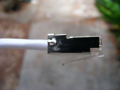
Cut the CAT5 cable to approximately 10 inches in length. Crimp a connector on one end. For better conductivity when using shielded cable, solder the drain wire to the connector shield as shown in the photo below.
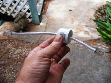
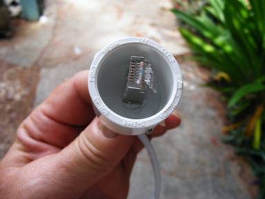
Now pass the cable through the hole in the top cap from the inside part of the end cap to the outside. If you are not going to use the optional heat shrink tubing, you may crimp the second connector on at this time (don't forget to solder the drain wire on this also). The result should look like the photo below.
Now apply a small bead of PVC cement about 1 inch behind the connector on the inside of the end cap as shown in the photo below.
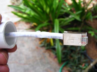
Now carefully pull the cable from the outside to bring this glue bead into the end cap so that it forms a bead around cable and hole. The connector should be nearly flush with the bottom of the end cap with only around 1/8 to ¼ inch of cable between the connector and the end cap. See photo below
Allow about 30 mins for the cement to dry. Then apply some of the PVC cement to the top side of the end cap and allow this to dry for a minimum of 2 hours. Then apply the liquid tape or other coating over the outside PVC cement to make it UV resistant. Allow this to dry.
If you are using the optional heat shrink tubing, apply and shrink this now. Crimp the final connector on the outside end if you did not already (don't forget solder).
The bottom end cap is now cemented to the PVC pipe that you cut in the first step.
Optional cable grommet installation: If you will be installing this protector in a location in which a radio has already been installed, you may want to install the cable grommet included in the DIY kit, as this will allow you to install the protector without cutting and replacing the CAT5 connector on the end of the cable. To do this you will need to expand the hole on the bottom section to ¾ inch diameter. The grommet will snap into place in this hole. Optionally, you can glue this into place using a few drops of PVC cement or Gorilla Super Glue (this stuff is amazing). It's easer if you do this before gluing the pipe to the end cap.
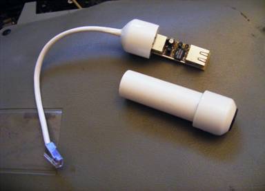
Thats it, you have an enclosure. Simply insert the protector module with the chip end up into and onto the connector with the pigtail glued to the top end cap.
The result should look like the photo below: